

Prodcuts
Contact
Tel: +86-519-88381518
Tel: +86-519-88389757
Mobile: +86 18068528818
E-mail: cw@cwmotor.cn
Add: Hugang Bridge, Economic Development Zone,Changzhou, Jiangsu,China
BLD510
Product introduction
1.summary
Bld510 is a digital universal brushless DC Driver produced by our company. The driver adopts the latest speed PID and anti vibration algorithm, which has the characteristics of high speed stability, large speed regulation ratio and low vibration. With abundant external interfaces, pulse width, voltage and frequency speed regulation can be adopted, making control more convenient.
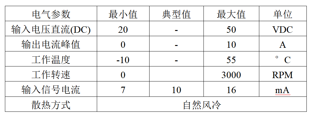
The driver voltage is DC 20v-50v, the maximum continuous current is 10a, and the maximum speed is 3000rpm.
2.characteristic
• high performance, low price
• high speed stability
• photoelectric isolation signal input / output
• low temperature rise and low vibration
• rich control methods
3.Electrical parameters
Interface wiring instructions
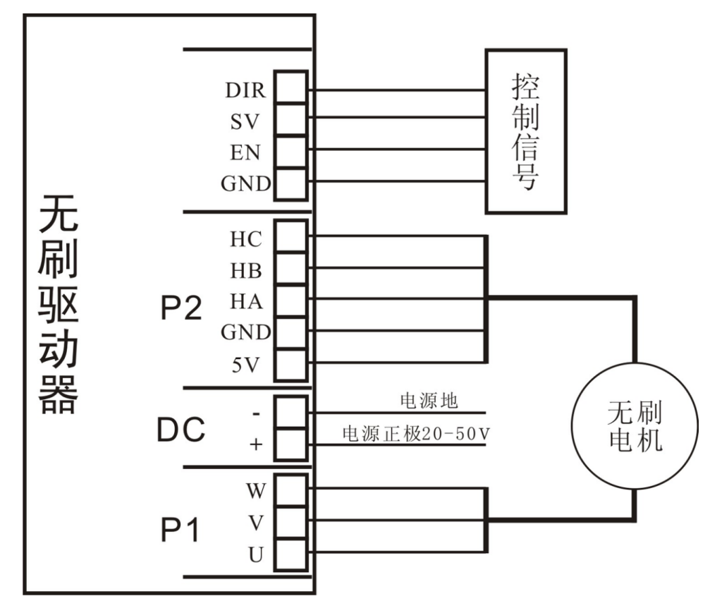
1.Power supply motor interface
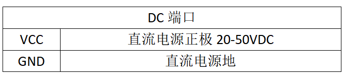
Make sure that the power line is wired correctly, and the reverse connection of the power line will cause damage or burnout of the driver.

According to the instructions of the motor, ensure that the UVW lines correspond one by one. The wrong connection of the UVW lines will cause the motor to fail to work normally, or the current is too large during operation.
2.Hall signal interface
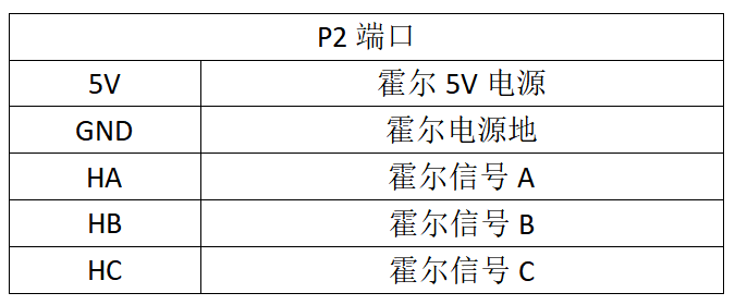
According to the instructions of the motor, ensure that the hall wires correspond one by one. The wrong connection of the hall wires will cause the motor to fail to work normally, or the current is too large during operation.
3. Control signal interface


The driver can adopt a variety of speed regulation and control modes, and the specific circuit and wiring modes are as follows:
3.1 adjustable resistance speed regulation
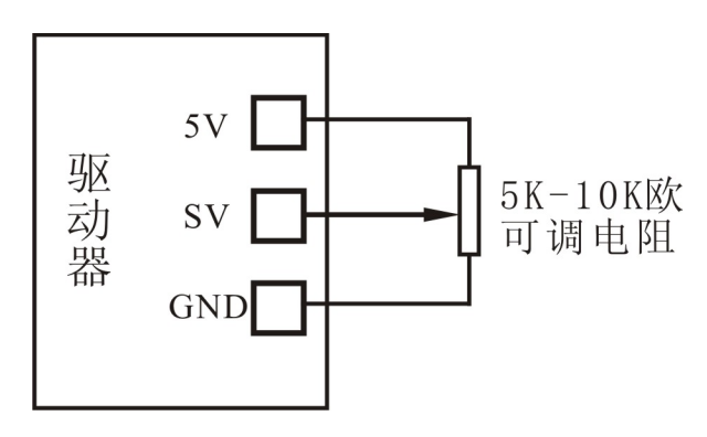
The value of adjustable resistance is better between 5k-10k. Before connecting the adjustable resistance, adjust the adjustable resistance to the middle position, and confirm the tapping sequence of both ends and the middle before wiring.
The adjustable resistance is not adjusted to the middle position or in the process of adjusting the resistance, the wrong connection will lead to a short circuit between 5V and GND. If the green light of the driver power is off or flashing, immediately cut off the power supply and detect the wiring.
3.2 external 0-10V voltage speed regulation
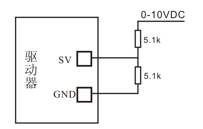
When inputting external voltage, it must be ensured that the voltage at the SV terminal does not exceed 5V at the maximum external voltage, otherwise the internal circuit of the driver will be burnt out. As shown in the figure above, with 5.1k partial voltage, when the external input is 10V, the voltage at SV terminal is 5V.
3.3 PWM duty cycle speed regulation
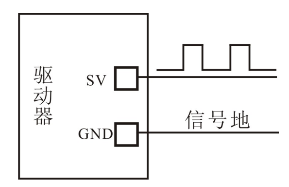
PWM duty cycle speed regulation, the input high-level amplitude cannot exceed 5V. If PLC control or other voltage control is used, please refer to 3.2 circuit connection.The PWM duty cycle is 0 to 100%, and the input frequency is between 1K and 20K.
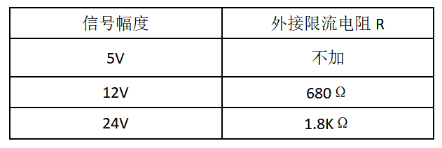
3.4 direction control signal
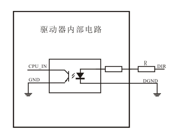
The direction input adopts optocoupler isolation, and the input voltage is 5V. If it exceeds 5V, the current limiting resistor R must be connected in series. See the table below for the value of R resistance.
3.5 alarm output signal
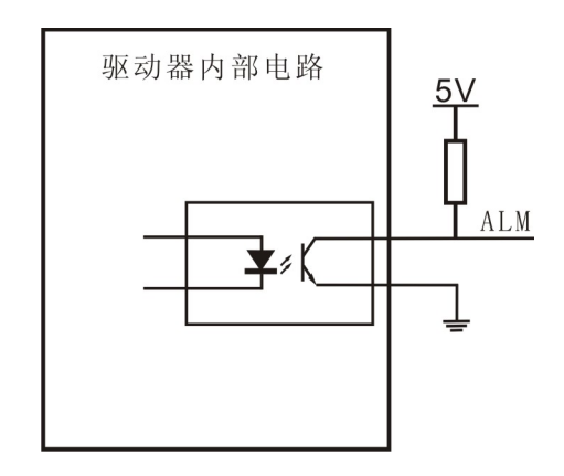
The alarm output adopts optocoupler isolation output, and the pull resistance should be added from alm to the controller end, as shown in the above figure. The alarm signal is low and effective.
3.6 start stop signal
The en signal is low and effective. The motor starts to run when it is connected to GND, and stops when it is disconnected from GND or connected to 5V voltage.
3.7 typical wiring diagram
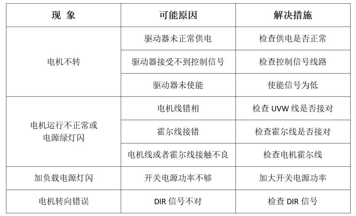
Common faults
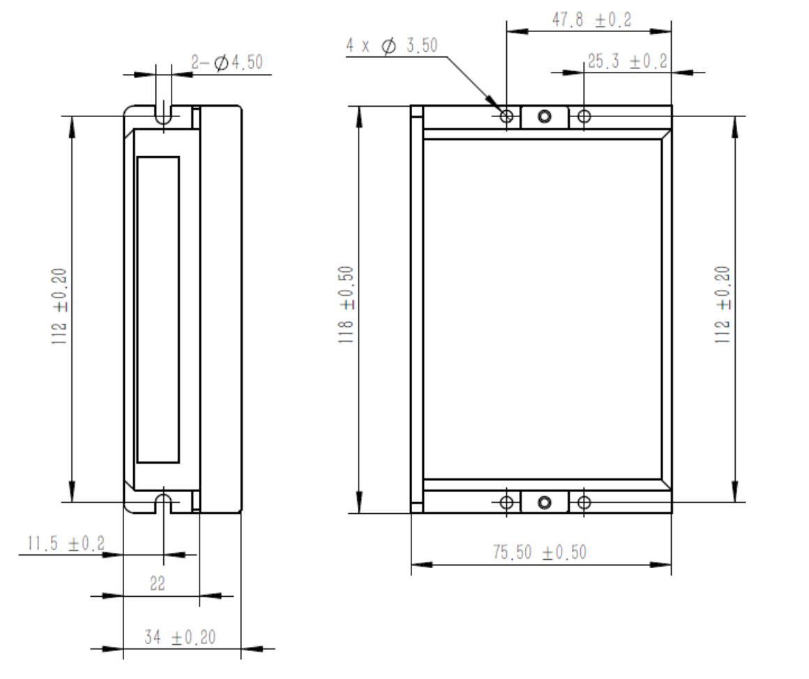
Outline and installation dimension (unit: mm)
The overall dimension of the driver is: 118 × seventy-five × 34mm, see the overall dimension drawing for details. Pay attention to leave more than 10cm space for heat dissipation. During installation, it should be close to the metal cabinet to facilitate heat dissipation.

Feedback


Contact
Mobile:+86 18068528818 (Elaine Yang)
Add:Hugang Bridge, Economic Development Zone,Changzhou, Jiangsu,China
![]()
Follow Us
Changzhou Chuangwei Motor & Electric Apparatus Co., Ltd Powered by: www.300.cn Changzhou 苏ICP备2021012447号-1