1. Descriptions
CWD882 is a new generation hybrid servo driver, it uses the 32-bit DSP processor, the internal integrates the technology of the anti-resonance, low noise, micro-step, low temperature rise ,so that dramatically improve the performance of the stepper motor,with some characteristics of low noise, small vibration, low temperature and high-speed torque . The driver's interior use the adaptive PID technology, without manual adjustment can automatically generate the optimal parameters for different motor, the motor runs to achieve the best performance.
Drive voltage is DC 24-90VDC, for various types of two-phase hybrid closed loop stepping motor which current is less 8.2A , with automatic semi-flow, self-test, over-voltage, under-voltage and over-current protection.
2. Features
• high performance, low price
• micro-step
• Automatic idle-current reduction
• Optical isolating signal I/O
•Max response frequency up to 70Kpps
• Low temperature rise, smooth motion
• Online adaptive PID technology
3.Applications
CWD882 is a low-cost, high-performance servo systems, suitable for a variety of large-scale automated equipments and instruments, such as low-cost, low vibration, noise, high-precision, high-speed devices, And it is ideal for applications where the equipment uses a belt-drive mechanism or otherwise has low rigidity and you don't want it to vibrate when stopping.
4. Electrical parameters

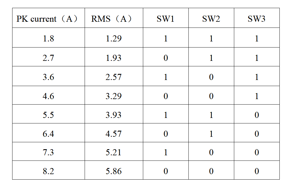
1. Current setting
Dial switch: on=0; OFF=1
2. Standstill Current Setting
SW4 is used for standstill current setting. OFF meaning that the standstill current is half of the dynamic current; and ON meaning that standstill current is the same as the selected dynamic current. Usually the SW4 is set to OFF, in order to reduce the heat of the motor and driver.
3. Subdivision setting
Dial switch: on=0, off=1

1. Control signal Connector(CN1)

If the input signal voltage amplitude is greater than 5V, the input terminal needs to be connected in series with a current limiting resistor (refer to the control signal interface circuit diagram).
2. Power and Motor Connector

3.The interface circuit of control signal